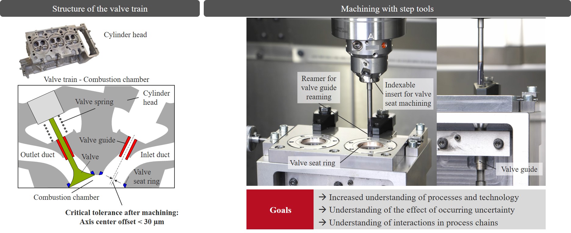
A suitable sequence of interlinked machining processes is the machining of the valve guide and the valve seat in the cylinder head of an internal combustion engine (see Figure 1). The complexity results from the interlinking of several uncertain machining steps, each of which has its own influence on the achievable bore quality. Starting from the cylinder head blank, the fitting bores for the valve guide as well as the valve seat insert are produced by means of simultaneous machining using a combination tool. Then, both the valve guide and valve seat ring are pressed in in the next process step. The final machining of the valve guide and seat also takes place simultaneously.
Due to the multi-stage interlinked processing, an extended spectrum of uncertainty arises. In industrial series production, the uncertainty of individual processing steps is not recorded for cost reasons. With today's state of the art, reliable machining can therefore only be guaranteed by extending the process chain with additional pilot processes, which in turn leads to an increase in cycle time and tool costs. In addition, single-bladed reamers are often used to achieve the required bore quality and are subject to strict limits with regard to possible productivity increases. As a result, it is necessary to take a holistic view of the interlinked machining processes. The relevant disturbance variables in the individual process steps must be identified and evaluated. The implementation of models for the simulation of machining processes represents a decisive step towards the control of uncertainty within the entire process chain.
Motivation
Precision Machining of Bores – Effect of Uncertainty
Fine machining of bores is the quality-determining process within a multi-stage process chain for the production of closely tolerated fitting and precision bores. A frequently used concept in this context is reaming, which processes an existing premachined bore to the intended final dimension. An advantage of multi-bladed tools is the increased productivity due to the increased feed per revolution, while single-bladed tools can be specifically adapted to the respective machining task, in particular by splitting the “guiding” and “cut-ting” functions. The basic investigations carried out so far identify four disturbance variables as relevant uncertainty in the fine machining of bores. On the one hand, this is a runout error that occurs, on the other hand an axis offset between the tool axis and the center axis of the workpiece, an inclined drilling surface and an inclined pre-machined hole. As a result of these disturbance variables, a radial force occurs which influences the dynamic behavior of the overall system. The result is a deterioration of the achievable bore quality with regard to the cylinder shape and the radial deviation, whereby the required tolerance cannot be adhered to.
The work carried out so far makes it clear that the uncertainty that occurs in the fine machining of bores has a significant influence on the achievable bore quality. In particular, the dynamic behavior of the tool can significantly impair the bore quality with regard to the circular and cylindrical shape as well as concentricity. There is a knowledge gap with regard to the influence of occurring disturbance variables to the extent that in industrial practice these generally have a superimposed effect on the process and thus influence the process dynamics. Also, a consideration of uncertainty within a process chain, in which several finishing steps follow one another, is not yet the subject of research.
Problems encountered in the manufacture of cylinder head components
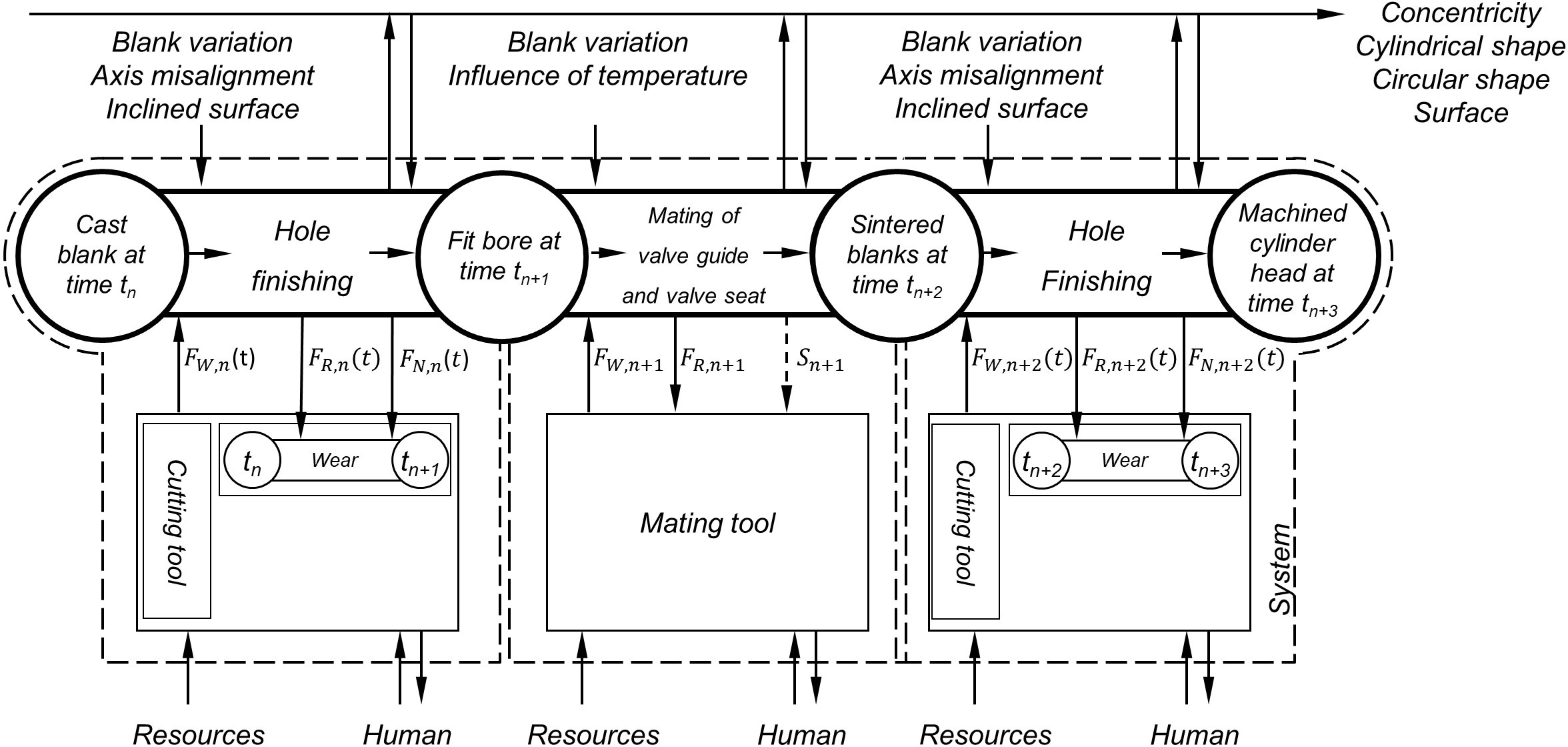
Finishing the valve guide and valve seat in the cylinder head is one of the most demanding tasks in automotive series production. Both components are exposed to high thermal and mechanical loads, which have increased significantly again in recent years due to the increase in the effective mean pressure within the framework of the specifications for reducing CO2 emissions and the downsizing effect of combustion engines. Until the 2000s, valve guides and valve seats were usually made of brass alloys, but today powder metallurgical manufactured components are often found in automotive series production. These are mainly components made of high-alloy steels with a hardness of more than 30 HRC. This leads to a sharp increase in cutting forces. At the same time, the tolerance specifications have been constantly tightened so that reliable machining can no longer be guaranteed without additional process steps. The processing of the components is a multi-level process chain (see Figure 2). In the initial state, there is an unmachined casting, usually made of an aluminium alloy. In a first step, fitting holes are machined into the cylinder head to join the valve guide and the valve seat. These are then pressed into the finished fitting bores under the action of force or via cooling of the valve guides and seat rings and finished in a final process step.
However, the resulting uncertainty – in the form of disturbance variables affecting the succession process – is not taken into account in automotive series production. Due to economic constraints, the quality parameters are not checked until after the finishing process has been completed. The dominant disturbance variables are an axis offset between the tool axis and the workpiece center axis and an inclined drilling surface. Both cause a deflection of the tool during the transient process phase, which can lead to failure to achieve the required bore quality. Even the development of a robust tool geometry does not allow process-safe single-stage machining of the valve guide.
Objectives and procedure
The overall goal of the transfer project T4 is the development of a holistic approach for the design of a process chain such as the machining of valve train components in the cylinder head of an internal combustion engine based on the methods developed in SFB 805. Uncertainty is controlled by the use of machining tools optimized under uncertainty aspects and adapted machining strategies. With the development of decision methodologies, a targeted selection of robust tools can be made and the optimum machining sequence for the respective process chain can be selected. In addition to an increase in machining quality, this is also associated with an increase in productivity.
The implementation methods are based on the findings from the first two funding periods of SFB 805. However, these findings must be systematically expanded by considering a complex process chain. The effects of machining operations carried out in the subsequent process steps must be taken into account in order to be able to control the uncertainty in the entire process chain and thus enable process-reliable machining sequences.
Intermediate results
Modeling
The analytical-empirical model developed within the framework of SFB 805 for predicting the quality of the machined components is subdivided into several submodels which are run through in a calculation loop with a fixed step size (see Figure 3).
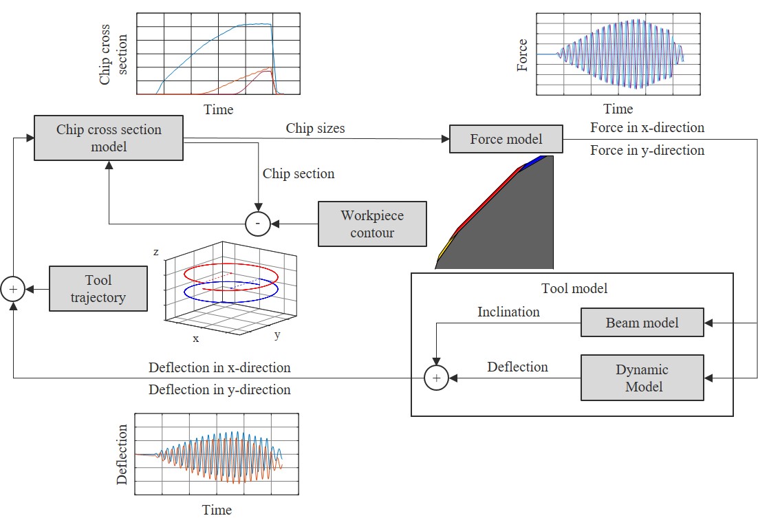
At the beginning, the tool paths and the workpiece contours are generated taking into account the geometric and technological boundary conditions as well as uncertainty in the form of superimposed disturbance variables. These serve as input variables for the subsequent calculation loop. The mathematical description of the chip cross section and the associated chip sizes is carried out using the chip cross section model. The chip cross section correlates with the mechanical load on the tool cutting edges as a function of the technology parameters, the tool geometry and the uncertainty due to the influence of disturbance variables. This correlation is represented by the empirical cutting force model. The vectorial added forces of the individual cutting edges in the three coordinate directions form the input variables into the tool model. The basis for mapping the dynamic properties of the tool structure is a motion differential equation. The forces acting on the tool structure deflect the tool in the spatial directions perpendicular to the tool axis. The total deflection causes a change in the tool path and thus ultimately a change in the chip cross section at the individual cutting edges. The models are parametric and can be extended for future applications.
Influence of the axial run-out of the drilling surface
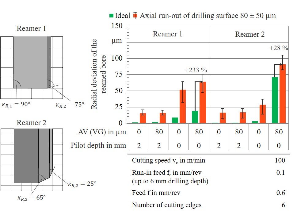
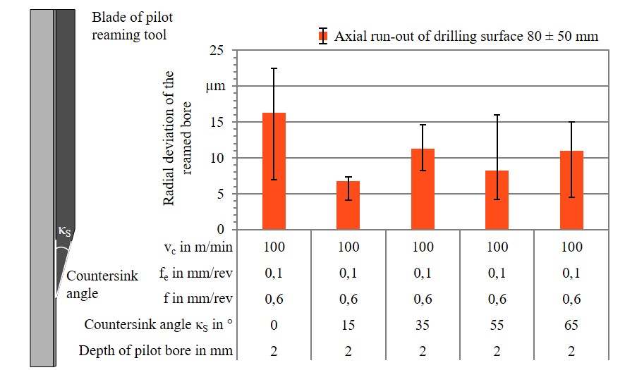
In industrial practice, an inclination of the drilling surface and a resulting deterioration in axial run-out occurs, among other things, due to clamping and reclamping processes of the workpieces on the individual machine tools within the production process chain. In addition, the blanks are often only provided with general tolerances in the range of 0.1 to 0.2 mm with regard to their axial run-out after passing through the powder metallurgical manufacturing steps and no further pre-processing of the boring surface takes place regularly. The random measurement of the axial run-out showed a deviation of 80 ± 50 μm. The results show a significant influence of the axial run-out of the drilling surface on the radial course of the reamed bore (see Figure 4). Irrespective of the cutting geometry, both tools react sensitively to a deterioration in the axial run-out of the drilling surface. On average, the radial deviation of the reamed bore increases by a factor of nine.
The results obtained bring the geometric design of the pilot reamer into the focus of further investigations. One way of countering the uncertainty caused by the deterioration in the axial run-out of the boring surface is to attach a countersinking step to the pilot reamer. The countersinking stage is axially reset in comparison to the friction cutting edges. The results obtained in the simulation show that the adaptation of the geometry of the pilot reamer has a significant influence on the radial course of the reamed bore (see Figure 5). If a chamfer angle of κS = 15° is selected, the reamer displacement can be reduced by 60 % to between 4 and 7 μm. This significantly increases process reliability. For a holistic consideration, the given boundary conditions with regard to permissible position and position deviations must be taken into account in order to achieve a unit cost-optimal solution.
Recommendations for action for tool design and process design
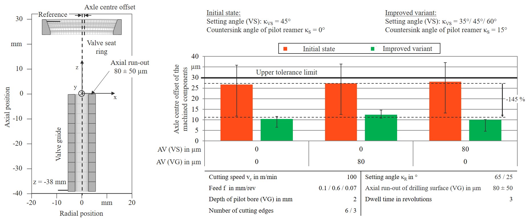
The systematic variation of process parameters and the quantification of the influence of uncertainty on the axial offset of the valve seat and valve guide offers the possibility of deriving fundamental recommendations which can be used in industrial practice as a starting point for a customer-specific design of the tool systems. The recommendations are summarised in Table 1 below.
Table 1: Recommendations for the design of tool systems for machining valve guides and valve seats
| Processing step | Recommendations for action |
|---|---|
| Pilot drilling by means of pilot reamer | Modification of the tool geometry by applying an axially offset countersink chamfer |
| Machining the valve guide using reamers |
Reduction of the entrance feed rate in the event of disturbance variables to ensure reliable machining even with progressive tool wear Use of tools with a small lead angle in combination with an adapted geometry of the pilot reamer |
| Machining the valve seat using indexable inserts |
Processing of two secondary angles for compensation of uncertainty due to disturbance variables Adaptation of the geometry according to requirements to reduce process forces Use of adjustment adapters to minimize the runout error of the tools |
In comparison to the validation tests, the consideration of the recommendations leads to a significant reduction of the axle center misalignment even under uncertainty (see Figure 6). The application of the process simulation thus enables a cost-effective and at the same time comprehensive investigation of various influencing factors on the achievable quality of the machined components.
Subproject Managers
| Photo | Name |
|---|---|
|
A
| Prof. Dr.-Ing. Eberhard Abele |