The cylinder head’s valve guide is used to guide and position the alternating valve in such a way that it seals the combustion chamber together with the valve disc and the valve seat insert. The valve guide and the valve seat insert are made from high-temperature powdered metallurgically manufactured steel. These two components are pressed into the cylinder head. The disturbance variables occurring from the components’ manufacturing processes and the pilot-hole’s position deviation, due to shrinking, overlap. The disturbance variables’ impact shows as an offset between the tool and the valve guide and as an inclined scored area as well as a scored alignment of the valve guide.
Summary
Uncertainty analysis during the parallel processing of cylinder head components
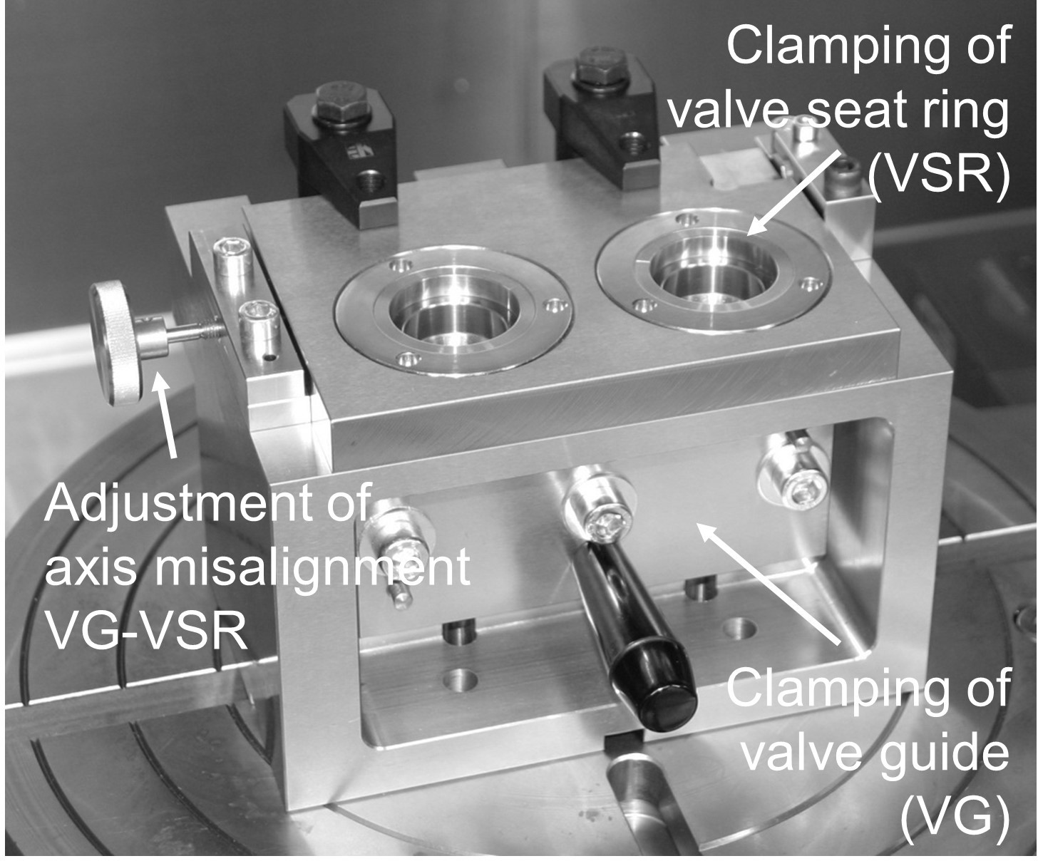
This project started with the identification and quantification of the occurring uncertainty in the serial production during the parallel processing. An axis offset occurs due to the overlapping deviations of the centres of the pressed sinter bushes and deviations from the cylinder head’s clamping process onto the workpiece carrier. According to specifications of the automobile manufactures, this axis offset between the component and the component carrier can amount to 0.1 mm in both axial directions. Another identified uncertainty due to the parallel processing is the centre deviation to both sides from both processed sintered components, the valve guides and the valve seats. Examinations with reamers, with a diameter of 6 mm, have identified this axis offset as the mayor disturbance variable. This result is supported by a sensitivity analysis carried out during subproject B3. An occurring axis offset causes a significant deterioration of the concentricity of the reamed valve guide. An ideal process features a concentricity of 15 µm over a drilling depth of 40 mm. This concentricity declines to 60 µm with an axis offset of 80 µm. For this reason, a device to illustrate the model process was developed. This device enables a continuous variation of the axis offset which can be configured independently for both sintered components (see image 1).
Wear optimised tool geometries to assure component quality
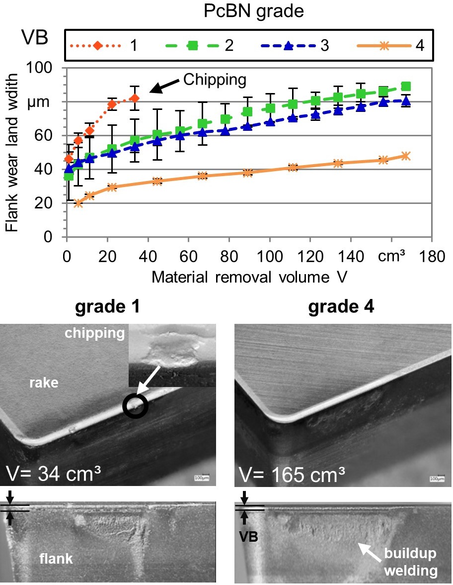
The experiments concerning the wear behaviour were given a high priority during this project. The cutting materials, which were used at the beginning of this project, showed during the use of new sintered materials, for the application at the valve seat, the tendency to mechanically failures in form of chipping along the cutting edge. The used sintered materials show a high level of hardness greater than 40 HRC. Therefore, it was a priority to determine the suitable microgeometry in combination with a wear optimised cutting material. During the full fractional test series, the cutting material, the effective angle of rake (negative chamfer), the length of the negative chamfer, and the clearance angle were varied. On the one hand, polycrystalline diamond (PCD 1) was used, on the other hand the tests were carried out with six different types of polycrystalline cubic boron nitride (CBN 1-6). The results of this test series showed that despite the application of emulsion cooling lubrication the use of PCD for the valve seat machining is impossible. The PCD cutting material already showed a flank wear of 125 µm at a material removal volume of 4.000 mm³. All CBN-based cutting materials did not reach these numbers even at a material removal volume of 165.000 mm³ (corresponds with approximately 4000 machining operations). The tests showed that the CBN cutting materials must be used with a negative effective angle of rake in combination with a rounded cutting edge to avoid chipping and to obtain the best results. Overall, the different CBN types showed similar wear behaviours, whereas CBN1 showed the least flank wear at the end of the experiments. Therefore, this cutting material was selected as the preferred cutting material for the following work packages (see image 2).
Implementation of a simulation model for the development of robust tools
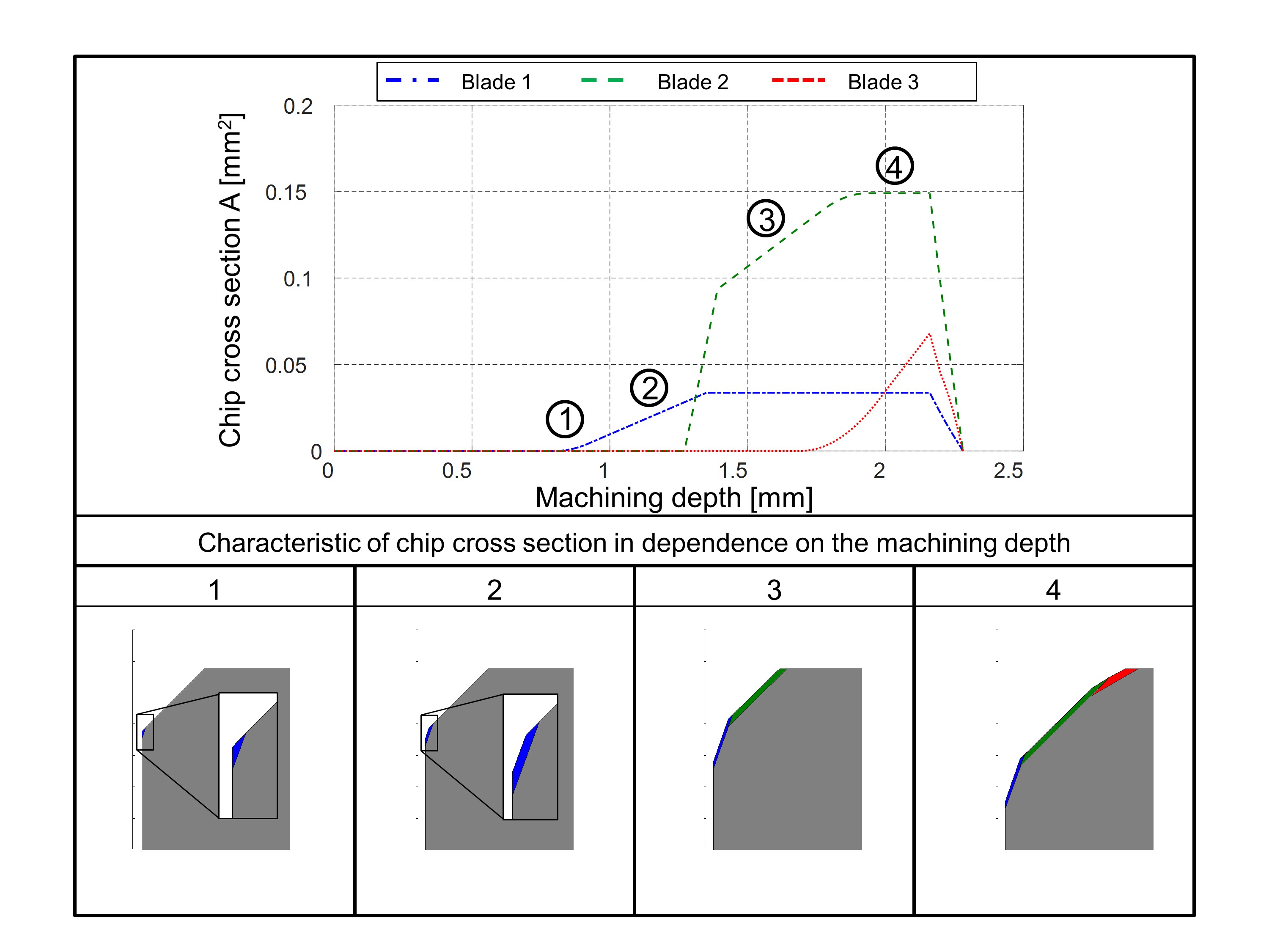
In the frame of this transfer project the already existing cutting force model from the first funding period was expanded for the reaming process regarding the parallel processing. For this reason, the force model for the cutting material CBN1 was expanded by varying the cutting speed, the feed, and the adjustment angle. The model of the chip cross-section, which was also developed during the first funding period, was expanded with the aspects of the cutting edge entrance and with the possibility to parallel machine the valve guide and the valve seat. Furthermore, the uncertainty due to the occurring disturbance variables in the form of an axis offset, a concentricity error and an inclined scored area was explicitly considered during the modelling. In this way, the individual disturbance variables can overlap as it is the case in the industrial practice. These results highlight (see image 3) that in comparison with the reaming process a stationary state cannot occur during the machining of the valve seat due to the radial and axial position of the cutting edges for the valve seat machining. Furthermore, it was shown that the entire process is subjected to the circumferential radial force with a varying load. This aspect must be considered during the implementation of a robust tool design.
Subproject Managers
| Photo | Name |
|---|---|
|
A
| Prof. Dr.-Ing. Eberhard Abele |